
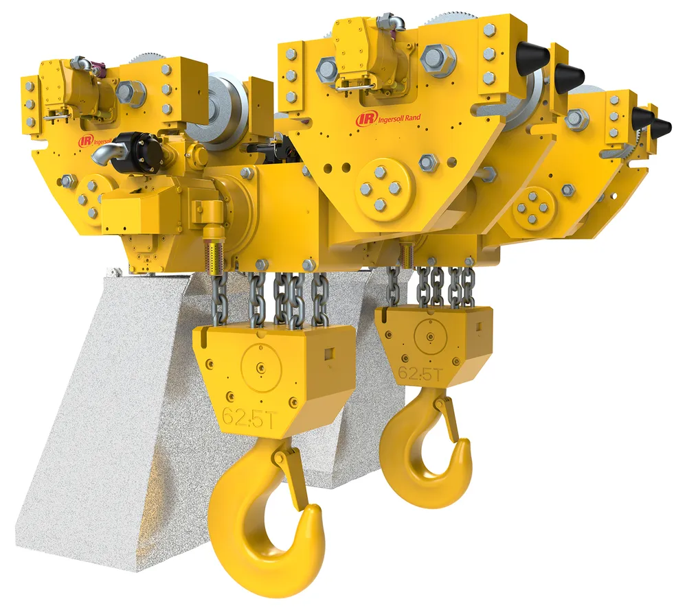
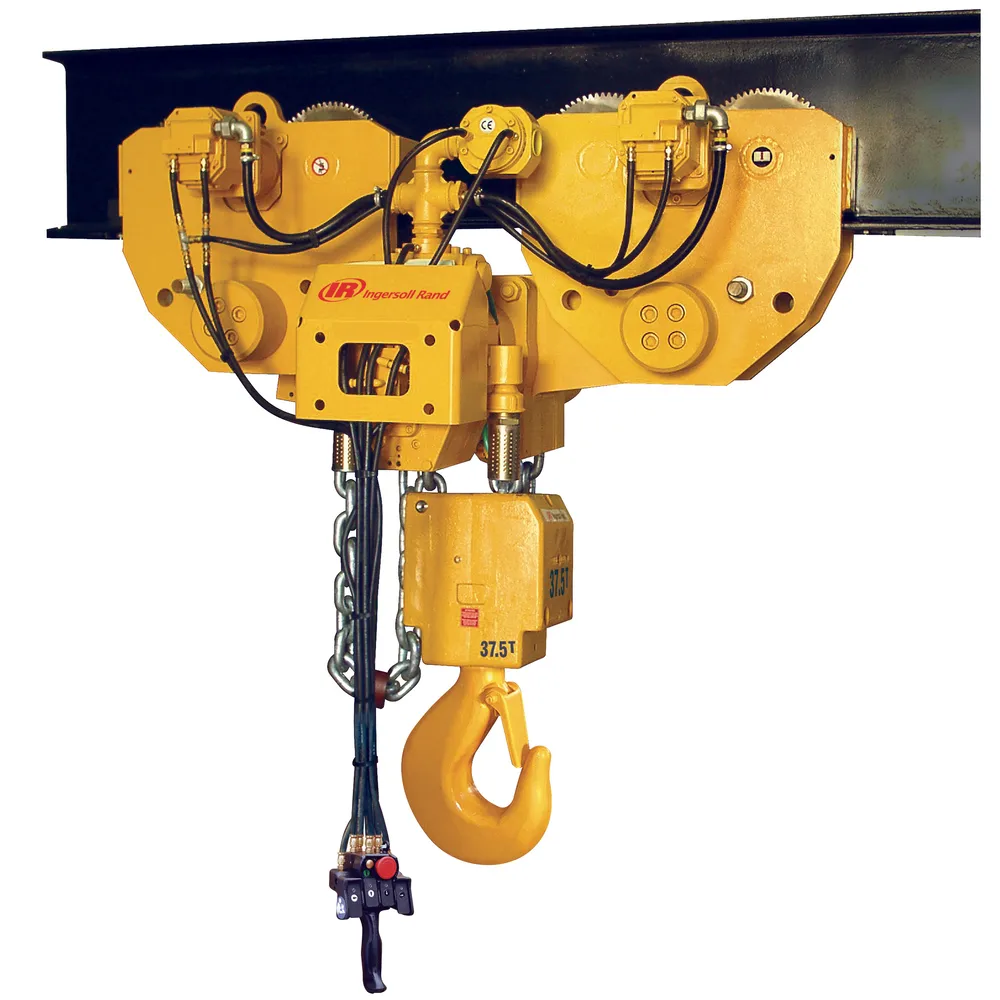
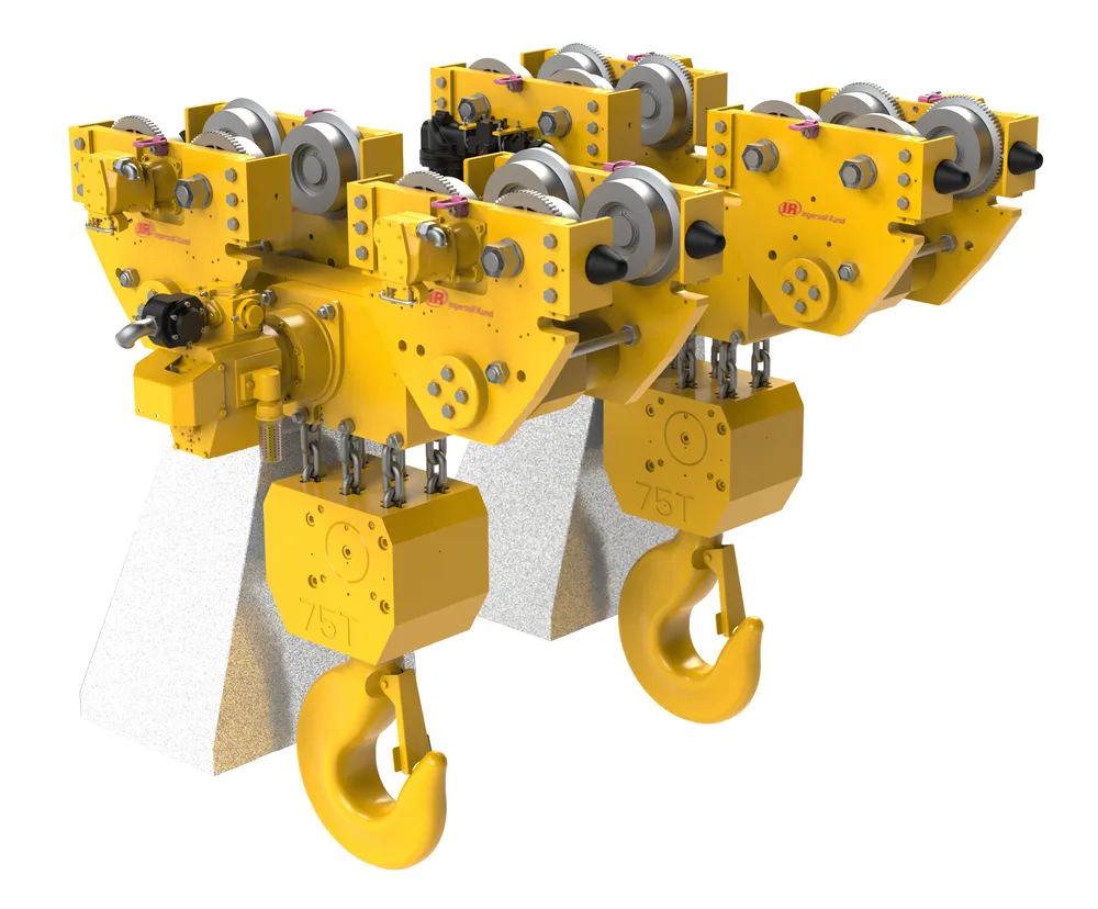
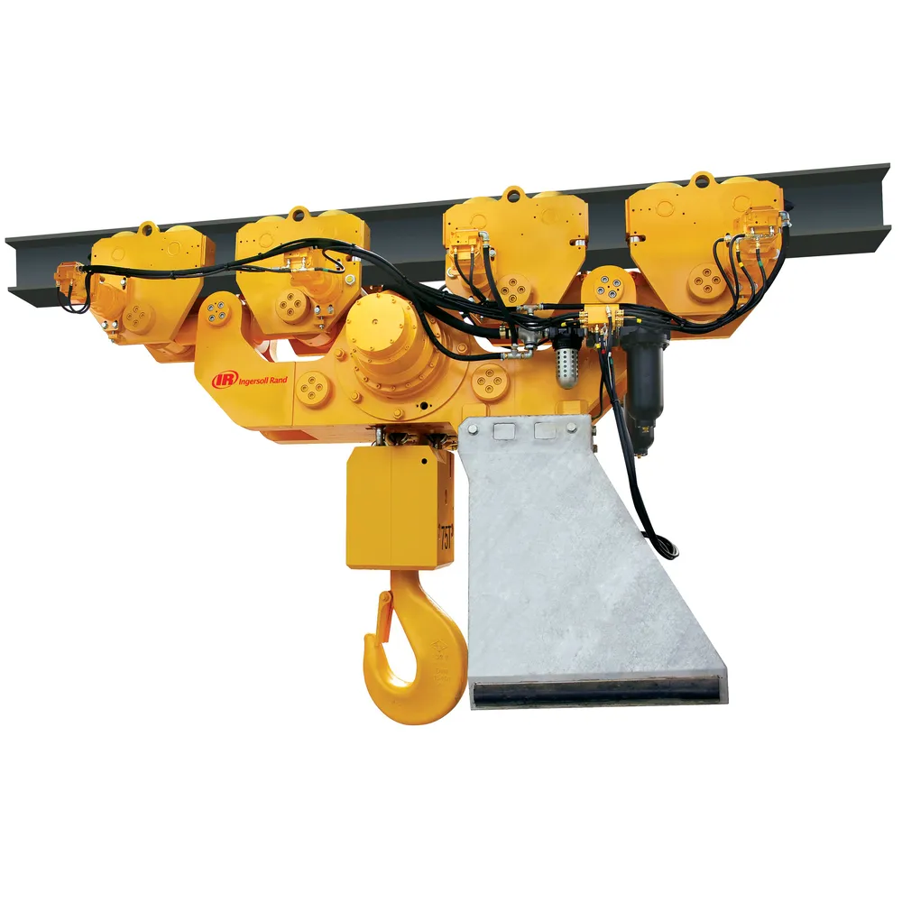

Features
Durability:
- Corrosion-resistant marine-grade paint
- Rugged all steel construction delivers long-life
- Corrosion-resistant load chain
- Available with either Gear (BS series) or Piston (BHS series) air motors which are recognized for decades for their durability, highly progressive speed and low maintenance cost
Safety:
- Automatic fail-safe, multi disc motor brake on hoist
- Ergonomic pendant with optional emergency stop/start feature
- Limit switch for upper and lower over-travel protection
Performance:
- Bottom block mounted on bearing with external lubrication point and water drain
- Available with clevis and shackle attachment or bottom hook
- Driven by reliable, virtually maintenance-free air motor
- Articulated trolley allows up to 20 degree side pulling operation
Model Specifications
Model | BS25LC2H2 | BS30LC2H3 | BS36LC2H3 | BS40LC2H4 | BS50LC2H4 | BS50LC2H2 | BS75LC2H3 | BS100LC2H4 | BS125LC2H5 | BS150LC2H6 | BS150LCH3 | BS200LCH4 |
|---|---|---|---|---|---|---|---|---|---|---|---|---|
Capacity(metric tons) | 25 | 30 | 36 | 40 | 50 | 50 | 75 | 100 | 125 | 150 | 150 | 200 |
Falls of load chainper hoist | 2 | 3 | 3 | 4 | 4 | 2 | 3 | 4 | 5 | 6 | 3 | 4 |
Min. headroom(in) | 44.7 | 47.6 | 47.6 | 48.8 | 48.8 | 41.1 | 46.9 | 48.5 | 54.5 | 59.8 | 73.4 | 77.2 |
Lifting speed at rated load(fpm) | 6.2 | 4.1 | 4.1 | 3.6 | 3.6 | 7.4 | 4.9 | 3.6 | 3.0 | 2.5 | 1.6 | 1.1 |
Lifting speed at no load(fpm) | 6.2 | 4.1 | 4.1 | 3.6 | 3.6 | 7.4 | 4.9 | 3.6 | 3.0 | 2.5 | 1.6 | 1.1 |
Lowering speed at rated load(fpm) | 6.2 | 4.1 | 4.1 | 3.6 | 3.6 | 7.4 | 4.9 | 3.6 | 3.0 | 2.5 | 1.6 | 1.1 |
Working pressure(PSI) | 1813 | 2103 | 2103 | 2103 | 2103 | 2538 | 2610 | 2683 | 2755 | 2828 | 2175 | 2610 |
Calibration pressure(PSI) | 2465 | 2538 | 2538 | 2538 | 2538 | 3045 | 3045 | 3045 | 3190 | 3190 | 3045 | 3045 |
Nominal flow(gpm) | 11 | 11 | 11 | 11 | 11 | 13 | 13 | 13 | 13 | 13 | 11 | 13 |
System weight(lbs) | 2208 | 3753 | 3753 | 4084 | 4084 | 6843 | 8609 | 9051 | 13024 | 13907 | 28256 | 28918 |
Chain size(mm) | 16×45 | 16×45 | 16×45 | 16×45 | 16×45 | 22×66 | 22×66 | 22×66 | 22×66 | 22×66 | 32×90 | 32×90 |
Model | BS25LC2A2 | BS30LC2A3 | BS36LC2A3 | BS40LC2A4 | BS50LC2A4 | BS50LC2A2 | BS75LC2A3 | BS100LC2A4 | BS125LC2A5 | BS150LC2A6 | BS150LCA3 | BS200LCA4 |
|---|---|---|---|---|---|---|---|---|---|---|---|---|
Number of wheels per hoist | 4 | 4 | 4 | 4 | 4 | 8 | 8 | 8 | 8 | 8 | 16 | 16 |
Std Flange adjustment(in) | 6,3-12,4 | 6,3-12,4 | 6,3-12,4 | 6,3-12,4 | 6,3-12,4 | 6,3-12,4 | 6,3-12,4 | 6,3-12,4 | 6,3-14,2 | 6,3-14,2 | 6,1-12,4 | 7-12,4 |
Max beam bottom flange thickness(in) | 1.6 | 1.6 | 1.6 | 1.6 | 1.6 | 1.6 | 1.6 | 1.6 | 4 | 4 | 1.6 | 1.6 |
Wheel tread diameter(in) | 6.3 | 8.9 | 8.9 | 8.9 | 8.9 | 6.3 | 8.9 | 8.9 | 9.8 | 9.8 | 8.9 | 8.9 |
Wheel loading per pair(lbs) | 13797 | 16556 | 19868 | 27594 | 27594 | 13797 | 20695 | 27594 | 34492 | 41391 | 20695 | 27594 |
Trolley Assy length(in) | 24.5 | 30.8 | 30.8 | 30.8 | 30.8 | 55.6 | 66.6 | 66.6 | 81.1 | 81.1 | 133.6 | 133.6 |
Number of motors per trolley | 1 | 1 | 1 | 1 | 1 | 2 | 2 | 2 | 2 | 2 | 4 | 4 |
Trolley air cons. Per hoist(scfm) | 67 | 67 | 67 | 67 | 67 | 134 | 134 | 134 | 134 | 134 | 268 | 268 |
Max travelling speed at rated load(fpm) | 39 | 49 | 49 | 39 | 39 | 39 | 39 | 39 | 30 | 30 | 33 | 33 |
Model | BHS50LC2A2 | BHS75LC2A3 | BHS100LC2A4 | BHS125LC2A5 | BHS150LC2A6 |
|---|---|---|---|---|---|
Number of wheels per hoist | 8 | 8 | 8 | 8 | 8 |
Std Flange adjustment(in) | 6.3 – 12.4 | 6.3 – 12.4 | 6.3 – 12.4 | 6.3 – 14.2 | 6.3 – 14.2 |
Max beam bottom flange thickness(in) | 1.6 | 1.6 | 1.6 | 4 | 4 |
Wheel tread diameter(in) | 6.3 | 8.9 | 8.9 | 9.8 | 9.8 |
Wheel loading per pair(lbs) | 13797 | 20695 | 27594 | 34492 | 41391 |
Trolley Assy length(in) | 55.6 | 66.6 | 66.6 | 81.1 | 81.1 |
Number of motors per trolley | 1 | 1 | 1 | 1 | 1 |
Trolley air cons. Per hoist(scfm) | 49 | 49 | 49 | 49 | 49 |
Max travelling speed at rated load(fpm) | 39 | 39 | 39 | 30 | 30 |
Trolley Selection
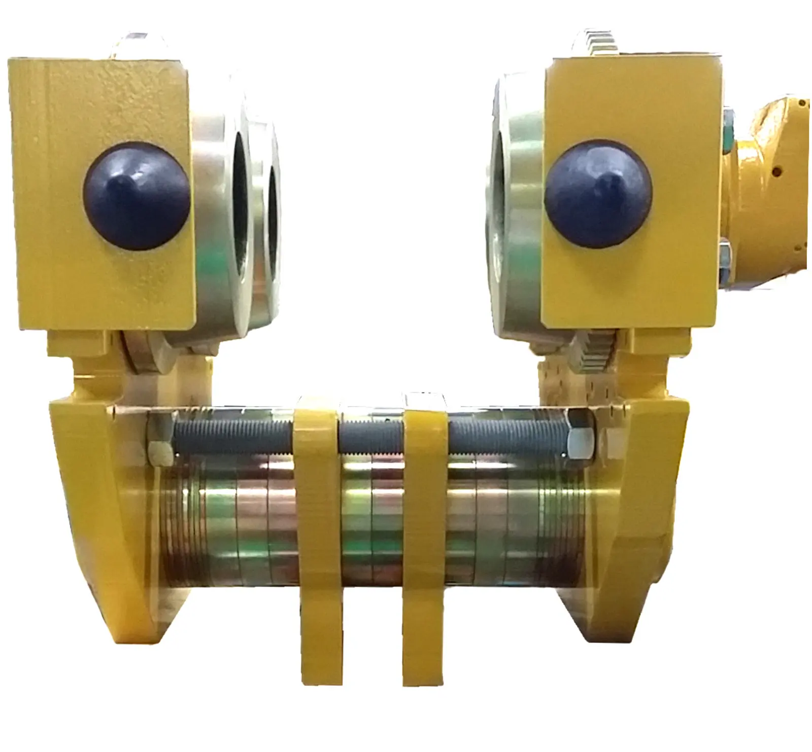
Using the right trolley size is crucial for your installation.
Ingersoll Rand has created two trolley sizes in order to match any configuration, even with large structural beams, for any specific situation.
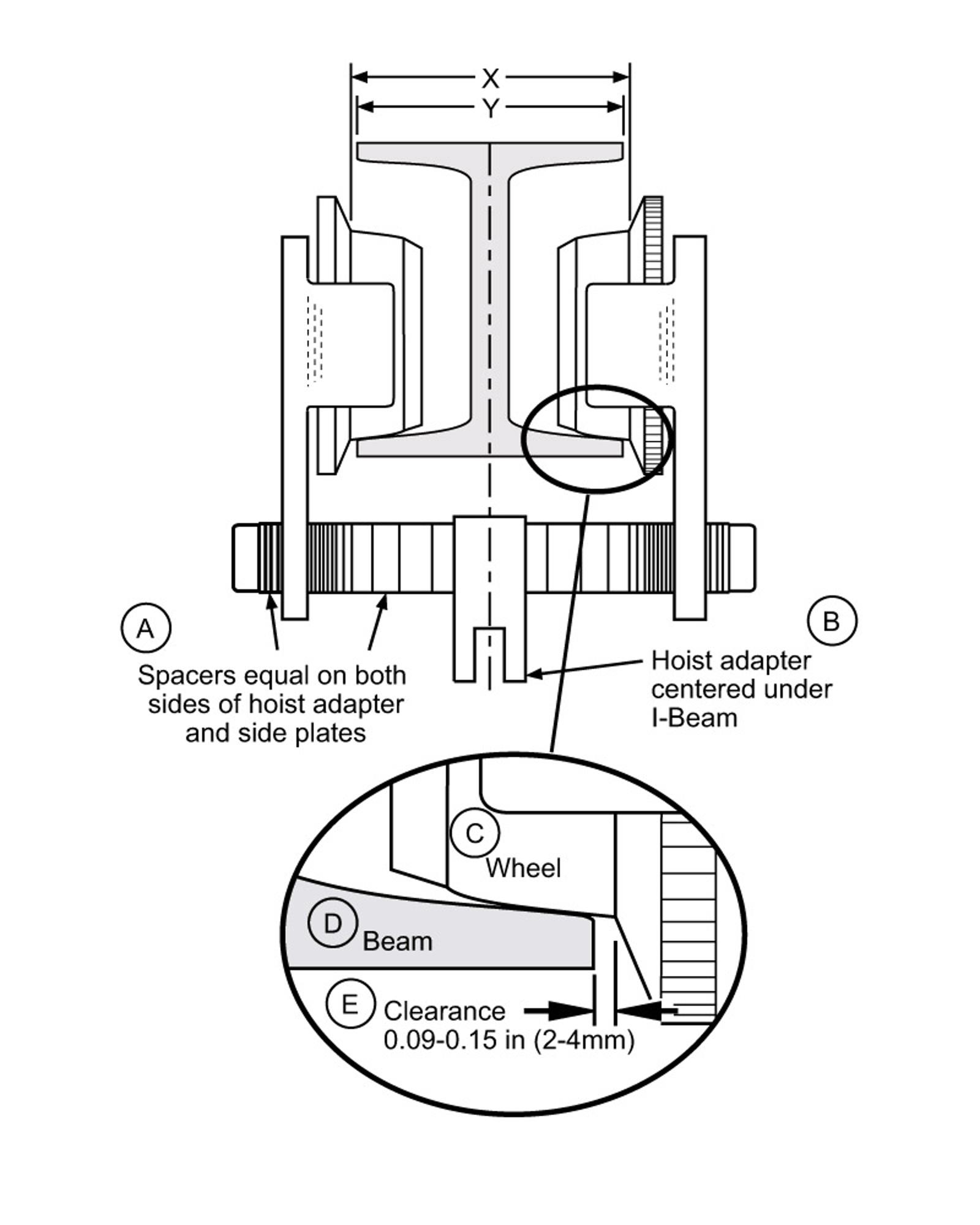
To select the correct trolley size, you need to check if your theoretical beam size “Y” plus the clearance “E” on each side of the beam is compatible with the flange adjustment range “X” shown in the standard Model Specifications tables.
For very large beams, an optional wide beam flange adjustment (option “W”) can be ordered. Please contact your Ingersoll Rand representative to order.
Series | Capacity (metric ton) | Flange Adjustment “X” (mm) | Maximum Bottom Flange Thickness (mm) | |
|---|---|---|---|---|
Standard | Wide (option “W”) | |||
BS | 25 | 130 – 314 | 315 – 410 | 40 |
BS | 25 / 30 / 36 / 40 / 50 (4 falls) | 140 – 314 | 315 – 410 | 40 |
BS / BHS | 50 (2 falls) / 75 / 100 | 160 – 314 | 315 – 410 | 40 |
BS / BHS | 125 / 150 (6 falls) | 160 – 360 | 365 – 410 | 102 |
BS | 150 (3 falls) / 200 | 170 – 314 | 315 – 410 | 40 |
LBS | 24.0 | 140 – 314 | 315 – 410 | 40 |
LBS | 36 / 50 | 170 – 314 | 315 – 410 | 40 |
ULBS | 100 | 270 – 314 | 315 – 410 | 40 |
ULBS | 150 / 200 | 200 – 314 | 315 – 410 | 40 |
ULBS | 250 | 200 – 360 | 365 – 410 | 102 |
Reviews
There are no reviews yet.