

Features
Air/Water-Cooled Aftercoolers
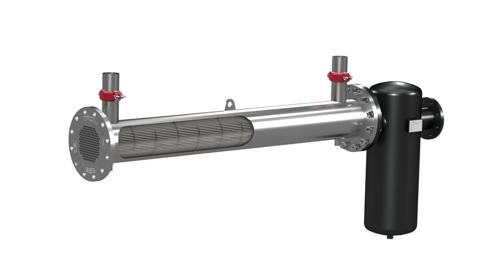
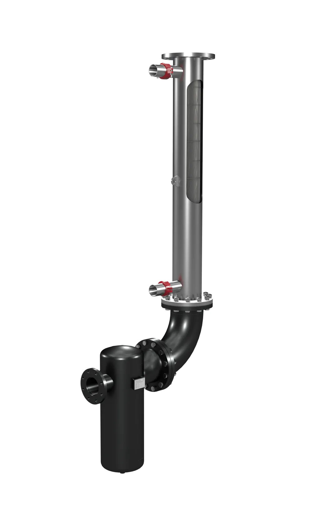
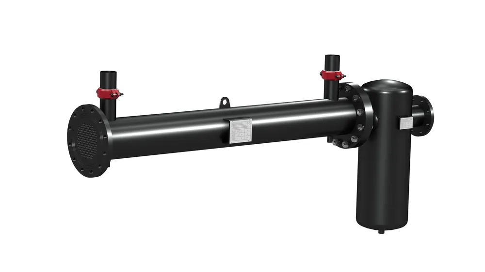
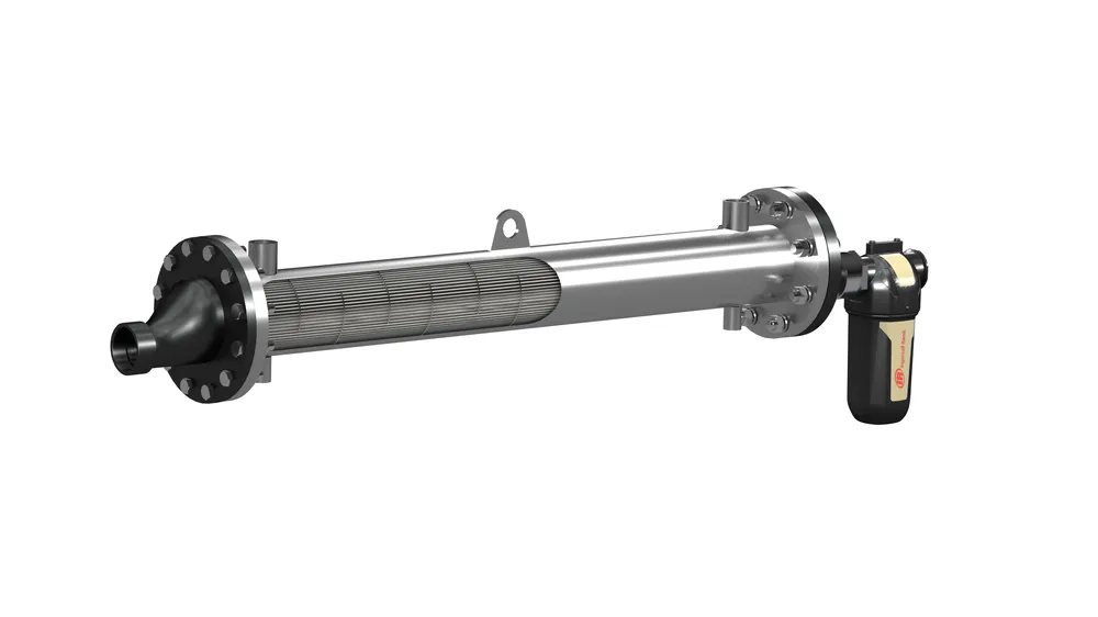
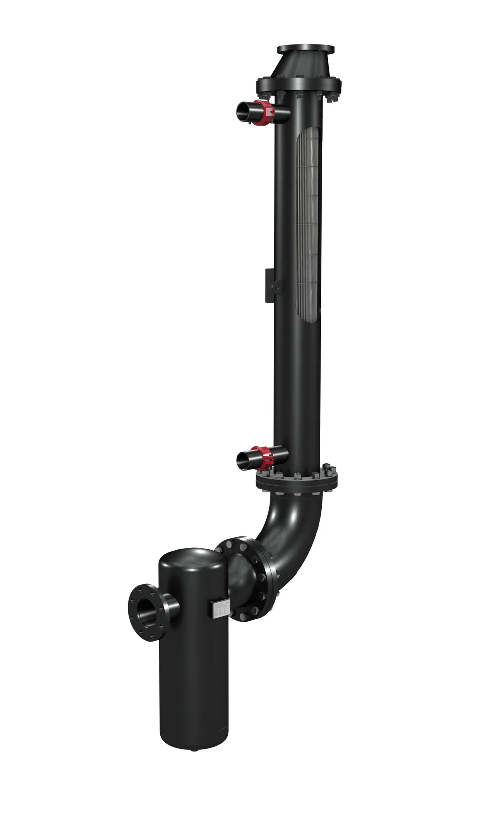
Water-cooled shell and tube aftercoolers can be used to cool compressed air easily and effectively. The counter-current heat exchanger allows the compressed air temperature to be reduced to the required conditions, optimising the downstream process. This is the case for adsorption dryers which prefer moderate inlet temperatures achievable with the WA. The air temperature obtained is slightly higher than the water temperature. Cooling compressed air, which is in most cases humid, leads to the formation of condensate, which can be separated by a condensate separator installed at the heat exchanger outlet. Separators included in aftercoolers up to WA350, have an aluminium body and cyclone cartridge and are equipped with an automatic floatcontrolled condensate drain. Separators from A450 onwards have a carbon steel body and a cyclone separator with manual drain. Reductions for connection to the compressed air system are optional.
Design Conditions
- Maximum compressed air inlet temperature: 200°C
- Maximum compressed air pressure: 16 bar
- Maximum water inlet temperature: 90°C
- Maximum water pressure: 10 bar
- Minimum ambient temperature: 1°C
Operating principle
In the heat exchanger, the compressed air flow passes through stainless steel pipes immersed in cold water, on the shell side. The cold water flow proceeds in countercurrent and is diverted by the diaphragms used to increase the heat exchange coefficient. The WA range, with an appropriate exchanger sizing, has limited pressure drops on the compressed air side, and simultaneous excellent thermal performance. The cyclone separator, installed at the tube outlet, provides a swirling motion that separates the condensate from the compressed air, conveying it by gravity towards the drain.
Specifications
WA27 to WA350
Models Max Air Flow
m3/hAir Inlet Connections
BSP / DNAir Outlet Connections
BSP / DNWater Connections
BSP / DNDrain Connection
BSPDimensions [mm] Weight [kg] A
A1
A2
B
D
E
L
H
WA
WAV
WA_S
WAV_S
WA27
160
DN100
1″1/2 BSPT
1″ BSP
1/4″ BSP
85
915
1000
356
114,3
548
1278
1555
34
52
34
52
WA42
250
DN100
1″1/2 BSPT
1″ BSP
1/4″ BSP
85
1065
1150
356
114,3
548
1433
1715
40
55
40
55
WA75
450
DN100
1″1/2 BSPT
1″ BSP
1/4″ BSP
85
1215
1300
357
114,3
548
1583
1865
45
58
45
58
WA125
750
DN100
2″ BSPT
DN40
1/4″ BSP
92
1300
1500
474
114,3
595
1831
2164
47
60
47
60
WA160
1000
DN125
3″ BSPT
DN40
1/4″ BSP
100
1400
1500
700
139,7
730
1929
2413
65
85
65
85
WA270
1600
DN125
3″ BSPT
DN50
1/4″ BSP
105
1445
1550
700
139,7
730
1979
2463
71
88
71
88
WA350
2100
DN150
3″ BSPT
DN65
1/4″ BSP
112
1488
1600
700
168,3
816
2044
2571
95
120
95
120
WA450 to WA6300
Models
Max Air Flow
m3/hAir Inlet Connections
BSP / DNAir Outlet Connections
BSP / DNWater Connections
BSP / DNDrain Connection
BSPDimensions [mm]
Weight [kg]
A
A1
A2
B
D
E
L
H
A
AV
A_S
AV_S
A450
2700
DN200
DN100
DN65
3/4″ BSP
112
1488
1600
840
193,7
1005
2120
2620
105
145
105
145
A560
3400
DN200
DN100
DN80
3/4″ BSP
112
1475
1600
840
219,1
1005
2120
2620
170
210
170
210
A800
4800
DN250
DN150
DN100
3/4″ BSP
137
1263
1400
995
273
1169
1975
2650
250
310
250
310
A1000
6200
DN250
DN150
DN100
3/4″ BSP
137
1262
1400
1014
273
1239
2045
2665
270
330
270
330
A1250
7500
DN250
DN150
DN100
1″ BSP
138
1513
1650
1049
273
1169
2365
2900
310
370
310
370
A1830
11000
DN300
DN200
DN125
1″ BSP
150
1500
1650
1258
323,9
1462
2415
3175
445
535
445
535
A2500
15000
DN400
DN250
DN150
1-1/2″ BSP
200
1350
1553
1463
403,4
1895
2540
3400
650
820
650
820
A3800
23000
DN450
DN250
DN200
1-1/2″ BSP
250
1350
1600
1689
457,2
2131
2720
3725
875
1100
875
1100
A5100
31000
DN500
DN300
DN200
2″ BSP
250
1500
1750
1961
508
2477
3100
4155
1510
1825
1510
1825
A6300
38000
DN600
DN350
DN200
2″ BSP
250
1500
1750
2041
609,6
2834
3235
4415
1625
2120
1625
2120
Performances & specifications: +/- 5%
WA = Horizontal – Painted. WAV = Vertical – Painted. WA_S = Horizontal – Stainless Steel. WAV_S = Vertical – Stainless Steel.
Performance referred to: Compressed air inlet temperature 120°C; compressed air inlet pressure 7 barg; water inlet temperature 15°C; compressed air outlet temperature 35°C.
Design conditions: maximum compressed air inlet temperature 200°C maximum compressed air pressure 16 barg; maximum water inlet temperature 90°C; maximum water pressure 10 bar; minimum ambient temperature 1°C.
Reviews
There are no reviews yet.